Electric automation is undoubtedly versatile and growing in industrial response and adoption. But that does not mean it is superior in every situation for every application. The idea that electrification is the straightforward way of the future can create circumstances where facilities select electric components by default, without a thorough assessment of what is best for their needs. It is important for plant engineers and integrating machine builders alike to resist the hype, and remember that each scenario is unique and should be considered in its own light.
The Safety Argument Is Not Marketing; It’s Physics
Any facility that contains or processes volatile organic compounds, combustible dust, or flammable gases must abide by a set physical rule: no sparks. Electric motors inherently spark; at the very least, a critical-to-operation relay must open and close, or a brush must come into contact with the slip ring. In fault conditions, they are effectively unrestrained arc-welders. Ensuring those sparks are suitably contained or eliminated within classified hazardous areas mandates construction of explosion-proof enclosures, strict adherence to complex installation wiring methods, and use of pre-approved and tested components. All of this considerably raises both the initial installed cost and subsequent maintenance burden for the system.
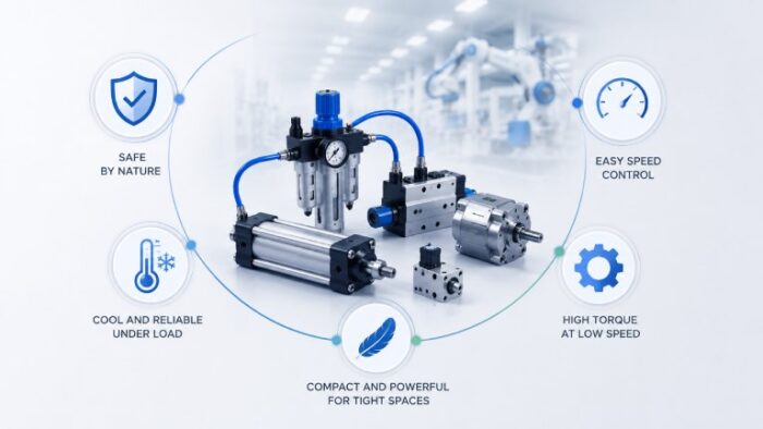
Pneumatics have no spark danger. There is no current of electrons cascading through the actuator or rotary motor to form an electric bridge needed for arc ignition. It does not exist; that’s why the equipment operates quite safely and ruggedly in explosive atmospheres where a single small explosion could become a chain reaction of substantial carnage. Chemical processors, paint sprayers, grain-handlers, and offshore oil producers are not putting their workers at risk, or trying to save a few bucks by allowing unsafe operating conditions when they specify pneumatic drives as the technology of choice. It flat-out delivers the requisite safety profile without any special engineering to block the known dangers reaching beyond the box.
Thermal Behavior Under Load is Where Pneumatics Genuinely Separate
When an electric motor stalls, meaning it is required to hold a position against a fixed load, current continues to flow through the windings, and heat is generated. If this continues for an extended period, the motor burns out. This is why in electric systems, you will see over-specified motors everywhere, and/or thermal protection circuits, and/or torque limited in software. Those are all real costs, both upfront and operationally.
By comparison, when a pneumatic motor stalls, the motor simply stops turning while air continues to flow into the motor chamber. The reason this is so critical goes back to thermodynamics: as a gas expands inside a chamber to create motion, heat is simultaneously pulled away from the chamber wall. This cooling effect is a fundamental part of the thermodynamic process that drives the motion.
Under a stall condition, when air is still free to flow and cooling is still active, the motor is under zero mechanical load and thus no thermal load. The stalling motor is no different from an idling motor. It can sit in this condition at stall torque indefinitely. This is a key requirement in countless applications: clamping, tensioning, pressing, or simply any drive which must sit in a loaded position for an extended period of time.
Power Density in Tight Spaces and End-of-Arm Tooling
Anyone who has attempted to integrate an electric motor in a robotic end-effector that must fit into a part or cavity, or within the physical form of a machine, understands the issue. Electric motors capable of generating the necessary torque for the application are large and heavy. An electro-mechanical gearbox is required for the desired output-speed-to-torque ratio. This increases both the motor length and weight. More often than not, the coupled motor and gearbox assembly place strain on the structural members of the host part, thus limiting the positioning system, and/or results in the assembly exceeding the payload ratings of the robot.
Pneumatic actuators deliver force and torque output comparable to that of electrical motors and gearheads at a physical volume that is a fraction of the size. The power-to-weight ratio of pneumatics is much better. This is why pneumatics currently dominate end-of-arm-tooling, pick-and-place, and any other application where the ‘robotic’ part is moving through its operational space. Lighter, faster robots equate to higher cycle rates, lower inertial and overhung loads on the drive motors and transmissions, and a smaller all-up machine-with-robotic-system footprint. This property carries over to linear motion as well. A pneumatic cylinder capable of exerting thousands of newtons of force can fit within an envelope. It would be impractical if using an equivalent linear electrical actuator; cost and ease of installation are also considered.
Rotary Applications, Variable Speed, and Starting Torque
In mixing, agitation, conveying, and similar continuous rotary applications, two performance characteristics matter most. The ability to deliver high torque at low speeds, and the ability to vary that speed without expensive drive electronics. Pneumatic rotary drives handle both through straightforward means.
Speed control in a pneumatic rotary system is managed by adjusting airflow with a simple flow control valve. No variable frequency drive is required, no programming, and no separate control cabinet. The adjustment is mechanical, infinitely variable within the operating range. It does not introduce the harmonic distortion that VFDs can put back onto an electrical distribution system.
A pneumatic gear motor delivers high torque at low shaft speeds without requiring an external gearbox in many applications. It does so while remaining fully safe in environments where a conventional electric motor would require specialized protection. In food processing facilities, chemical plants, or any area where moisture or airborne contaminants are present. The absence of windings, encoders, and control electronics eliminates entire failure modes. There’s no insulation to degrade, no encoder to contaminate, and no heat sink to pack with dust.
Starting torque is also worth addressing directly. Many pneumatic rotary motors produce their highest torque at or near zero speed, which is the opposite of many AC induction motor configurations that need to reach a threshold speed before developing full torque. For applications that start under load, conveyors that begin moving with material already on them. For instance, this characteristic reduces mechanical shock on the drivetrain and extends component life.
Surviving Conditions That Damage Electronics
Steel mills, glass manufacturing plants, foundries, and similar heavy industries subject equipment to radiant heat levels that could render standard electric motor insulation useless in a matter of hours. Pneumatic systems have no insulation to damage. The compressed air itself provides a degree of thermal isolation. The metal bodies of cylinders and motors are easy to cool by adjusting the air supply.
At the other end of the industrial extreme, every day food processing and pharmaceutical manufacturing facilities use regular washdown cycles, dousing equipment with high-pressure hot water and caustic cleaning agents. Electronic components fail fast under those circumstances. Motor windings and encoder housings specified to very high ingress protection ratings fail under those circumstances. And even when specified with IP ratings high enough to survive the thermal cycling and chemical assault. The seals of those components degrade quickly under regular washdown operation.
Pneumatic components in washdown environments need far less by way of special protection in order to survive. Stainless steel bodies, a handful of simple lip seals, and the positive internal pressure of the air supply itself do very well at keeping water out. In practice, this means longer service intervals and lower failure rates while maintaining a level of hygiene that is literally requisite for life itself.
Mechanical Simplicity as a Maintenance Advantage
A pneumatic cylinder or rotary motor is very low in parts count. A piston or vane set, a few seals, and a body. These components can be serviced by an individual with a basic understanding of mechanical principles and access to common tools. Seal replacement on nearly all pneumatic actuators can be accomplished in minutes rather than hours.
A servo-electric system contains all of the above pneumatic parts, plus windings, bearings, an encoder, a feedback cable, a servo amplifier with its own unique firmware, and communication wiring back to a controller. When a drive blows, its fault isolation requires an oscilloscope and technical training that the maintenance staff at any run-of-the-mill production facility does not likely possess. Repairs boil down to waiting for a special technician or sending the drive back to the manufacturer if you have no other choice.
This difference in maintenance expense is anything but subtle. In facilities that are packed with equipment and operate on thin margins and even thinner production windows. So being able to “throw a part” and service it with locally sourced parts and labor translates into shorter work orders and less expensive labor per unit of time on the equipment over its lifespan.
Smart Pneumatics and the Integration With Modern Plant Systems
The idea that pneumatics and digital control are two great tastes that do not taste great together is something like a five- or ten-year-old concept. Pneumatic equipment manufacturers have designed manifolds with integrated pressure and flow sensors, IIoT-capable IO-Link communications, and electronic proportional control valves. It can hold position to within tenths of a millimeter and send real-time feedback to a plant SCADA system. Pressure proportional and flow proportional control with these manifolds can dial pressure and flow up or down with a 4-20mA or digital control signal the same way electric actuators would, only with air power’s invulnerability to short circuits and thousands of meters from an ignition source.
Air Preparation is the Foundation That Makes All of This Work
Without proper air preparation, none of the performance characteristics listed above are consistently achievable. Filter, regulator, lubricator, FRL, at the point of use, and the compressed air entering an actuator or motor is clean, dry, of the correct pressure, and carrying the lubrication film necessary for seals and vanes to achieve the lifetimes manufacturers promise. For all its importance, this is the most skipped and undersized stage that we see in pneumatic systems.
The Competitive Reality For Plant and Machine Builders
Pneumatics and electric automation are not suited to fight for every control and actuation application. Certain types of tasks play to servo-electric’s clear strengths, ultra-high-precision multi-axis positioning systems, for example, or applications that require extremely high-resolution, closed-loop speed control combined with high torque. Tasks that must operate at sub-freezing or extremely high-temperature conditions are similarly unsuited for pneumatic control, as well as applications where installing an air supply is both cost-prohibitive and a logistical nightmare.
But there’s a large and durable segment of industrial motion and force applications where the thermodynamic self-cooling, the inherent explosion safety, the mechanical simplicity, and the washdown resistance of pneumatics make it the most practical and cost-effective solution available. Modern smart pneumatics extend that range further by adding digital connectivity without sacrificing the physical properties that made pneumatic power valuable in the first place. The engineers who understand both technologies and choose based on what the application actually demands are the ones who build systems that last.